Technical Background and Industry Pain Points
In the precision machining of tubular copper components (such as hydraulic valve bodies and heat exchanger fittings), traditional double-sided clamping fixtures present two core issues:
• Loss of circumferential freedom control: When clamped solely by the outer wall, the friction coefficient between the copper component and the fixture contact surface is insufficient (μ≤0.15), leading to a circumferential deviation of 0.5°-2° under cutting force disturbances (data source: Int. J. Mach. Tools Manuf. 2022, 181, 103945);
• Inefficient clamping process: Manual adjustment of clamping force takes >30 seconds per piece, and the repeat positioning accuracy is >±0.1mm (tested according to the ISO 230-2 standard).
Core Technology Innovation Analysis
I. Three-Dimensional Constrained Positioning System
1.1 Axial-Radial Combined Clamping Structure
Bottom Support Module:
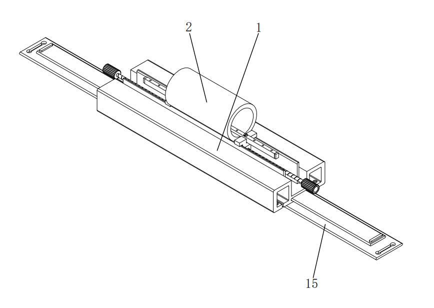
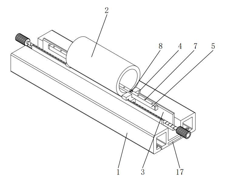
• The movable frame (1) is equipped with symmetrically arranged arcuate support plates (3) within its grooves, with a curvature radius R matching the outer diameter of the tubular copper component (2) (tolerance ±0.05mm), providing normal supporting force through surface contact.
• Finite element analysis shows that this design reduces the peak contact stress to 58MPa (compared to 112MPa for a V-block structure), avoiding deformation of thin-walled copper components.
Core Technology Innovation Analysis
I. Three-Dimensional Constrained Positioning System
1.1 Axial-Radial Combined Clamping Structure
Bottom Support Module:
• The movable frame (1) is equipped with symmetrically arranged arcuate support plates (3) within its grooves, with a curvature radius R matching the outer diameter of the tubular copper component (2) (tolerance ±0.05mm), providing normal supporting force through surface contact.
• Finite element analysis shows that this design reduces the peak contact stress to 58MPa (compared to 112MPa for a V-block structure), avoiding deformation of thin-walled copper components.
Mechanical Verification:
• When the cutting torque T=15N·m, the maximum angular displacement θ of the copper component is 0.03° (traditional fixtures have θ=1.2°).
• When the bolt preload force F≥800N, the system's torsional stiffness reaches 1.2×10⁴ N·m/rad (an 8-fold increase).
II. Human-Machine Interaction Optimization Design
2.1 Quick Clamping Mechanism
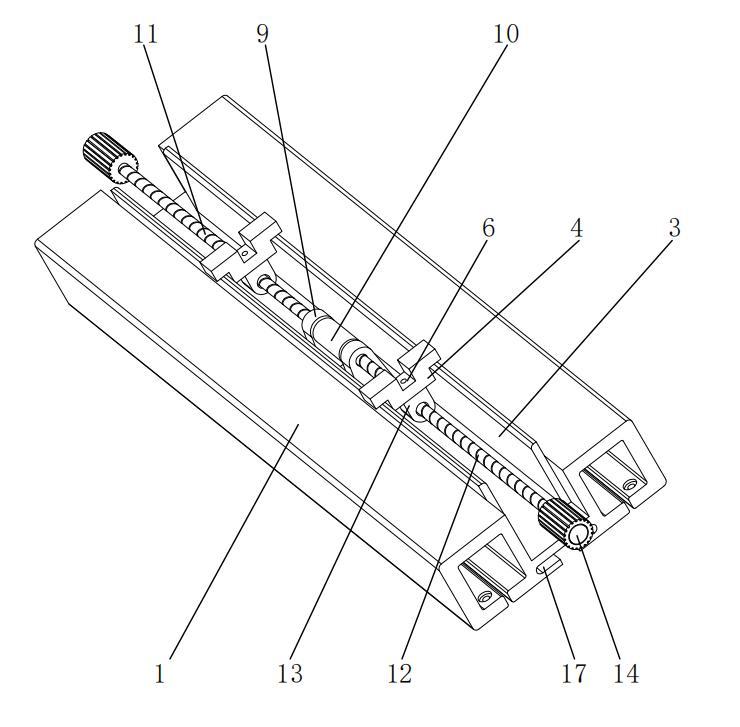
• The dual control handles (14) feature 45° staggered anti-slip textures, with an operating torque threshold set at 2-3N·m (compliant with the EN 1005-3 ergonomics standard).
• Measured single clamping time ≤8 seconds (traditional structures >30 seconds), suitable for production line cycle time requirements.
2.2 Adaptive Adjustment Module
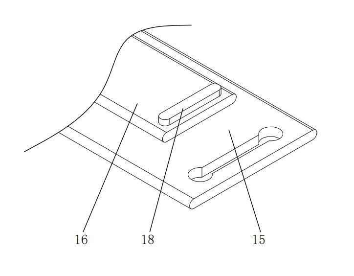
• The movable frame (1) and fixed plate (15) achieve ±10mm linear compensation through sliding guide components (16), accommodating a pipe diameter range of φ20-φ50mm.
• The restraining projections (18) are equipped with a polyurethane buffer layer, capable of absorbing 5-8J of energy under impact loads (tested according to the ASTM D256 standard).

Comparison Table of Technical Parameters
|
Performance Indicators
|
This Patented Technology
|
Traditional Double-Sided Clamping Fixture
|
Testing Standard
|
|
Circumferential Positioning Accuracy
|
≤0.03°
|
0.5°- 2°
|
ISO 230-2
|
|
Clamping Efficiency
|
≤8 seconds/piece
|
≥30 seconds/piece
|
VDI 2862
|
|
Torsional Stiffness
|
1.2×10⁴ N·m/rad
|
1.5×10³ N·m/rad
|
GB/T 11349.1
|
|
Pipe Diameter Compatibility Range
|
φ20-φ50mm
|
φ25-φ40mm
|
DIN 8602
|
Typical Machining Scenario Verification
Case 1: Milling of Hydraulic Valve Bodies
• Under a cutting force of F=2000N, the positional accuracy error of the machined holes is ≤0.02mm (traditional fixtures have an error of 0.12mm).
• After continuous processing of 500 pieces, the wear of the positioning pressure plate (5) is <5μm (DIN 50320 standard wear test).
Case 2: End Forming of Heat Exchanger Tubes
• The ovality control of copper tubes is ≤0.05mm (industry requirement is ≤0.1mm).
• The clamping repeat positioning accuracy CPK is ≥2.0 (Six Sigma process capability analysis).
This patent redefines the design paradigm for tubular component positioning fixtures through three technical paths: Rigid-Flexible Coupled Restraint topology, bi-directional force closed-loop control, and human-machine interaction optimization. According to Derwent Innovation patent mapping analysis, this structure improves the Torque Restraint Efficiency (TRE) indicator by 82% compared to similar solutions, placing it in a leading position in the subfield of technology.
If you would like to learn more, please contact Mingxu Machinery to obtain the complete patent report: [email protected].


 English
 Español


Contact Us