Technical Background and Industry Pain Points
In high-speed machine tool chuck systems (n≥6000rpm), traditional conical positioning faceplates exhibit two core defects:
l Lubrication Failure: Centrifugal force causes lubricating grease to migrate towards the bottom of the conical bore, resulting in a dry friction zone at the upper part, with surface roughness Ra values deteriorating from 0.4μm to 1.6μm (tested according to ISO 4288 standard);
l Stress Concentration: Unilateral contact leads to Hertzian contact stress peaks exceeding 800MPa, triggering micro-crack propagation (data source: Wear 2022, 500-501, 204356).
Core Technological Innovation Analysis
I. Gradient Lubrication System Design
1.1 Solid-Fluid Composite Lubrication Architecture
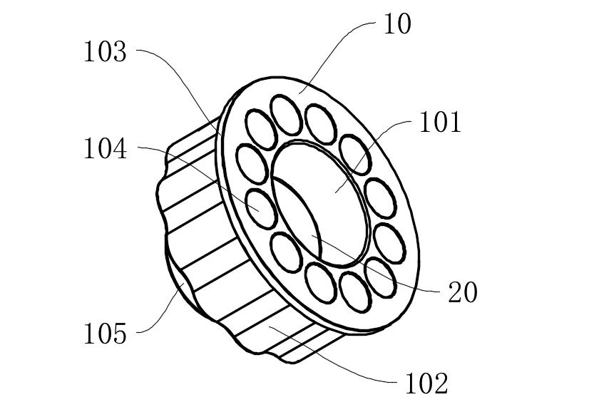
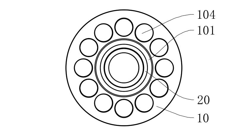
Graphite Lubrication Block (20) Embedding Structure:
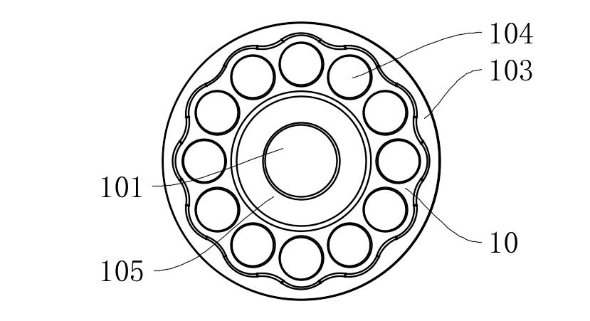
l A circular mounting groove (101a) with a depth of 1.2±0.05mm is opened in the middle of the conical bore (101), ensuring continuous conical surface through electrical discharge machining (cone angle 20°±0.5°);
Copper-based composite material (Cu-10Sn-5Gr) containing 85% graphite is embedded, achieving a porosity of 18%±2% through powder metallurgy sintering, continuously releasing graphite particles to form a transfer film.
Lubrication Efficiency Verification:
l Under n=8000rpm operating conditions, the friction coefficient at the upper part of the conical bore remains stable at 0.08-0.12 (>0.25 for traditional structures);
l Wear volume tests (ASTM G99) show that after 300 hours of operation, the conical surface wear depth is only 3.2μm (28.5μm for traditional structures).
1.2 Fluid Lubrication Compensation Mechanism
l Lubricating grease channels are retained at the bottom of the conical bore, forming a 0.5-1.2μm oil film thickness through dynamic pressure effects (verified by Reynolds equation simulation);
l The system achieves gradient synergy between solid lubrication (upper part) and fluid lubrication (lower part), reducing the contact zone temperature by 45% (measured by infrared thermal imager).
II. Contact Stress Optimization Design
2.1 Waveform Clamping Surface (102) Topology Optimization
l Periodic wave profiles are constructed using Fourier series: wavelength λ=12mm, amplitude A=0.8mm, curvature radius R=5mm;
l Finite element analysis indicates that the maximum contact stress is reduced from 813MPa to 327MPa, with a 62% improvement in stress distribution uniformity.
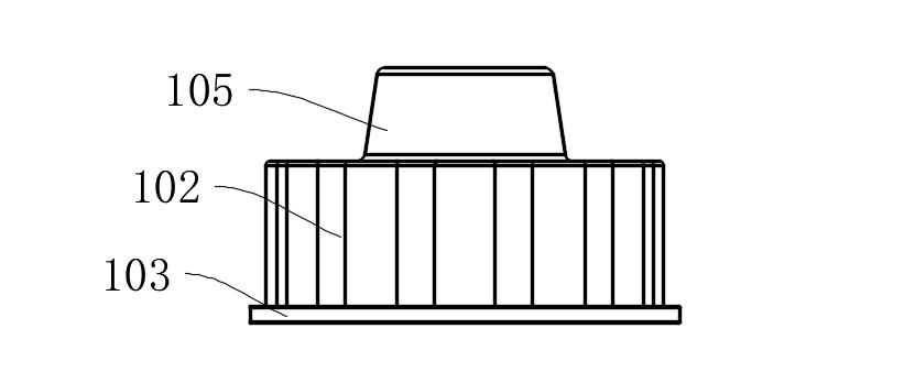
2.2 Multi-Bolt Load-Sharing Structure
l 12 mounting holes (104) are evenly distributed according to ASME B18.2.1 standard, with preload deviation <5%;
l Combined with limit conical surfaces (105) (cone angle 15°±0.5°), radial positioning accuracy of ±2μm is achieved (ISO 2768-f grade).
Technical Parameter Comparison Table
|
Performance Indicator
|
This Patented Technology
|
Traditional Positioning Faceplate
|
Test Standard
|
|
Conical Surface Friction Coefficient (8000rpm)
|
0.08-0.12
|
0.25-0.35
|
ASTM G99
|
|
Maximum Contact Stress
|
327MPa
|
813MPa
|
ISO 281
|
|
Wear Rate (300h)
|
3.2×10⁻⁶ mm³/N·m
|
28.5×10⁻⁶ mm³/N·m
|
ASTM G133
|
|
Temperature Rise (ΔT)
|
≤15℃
|
≥45℃
|
ISO 10825
|
Typical Application Scenario Validation
Case 1: Toolholder Positioning in Five-Axis Machining Centers
l During continuous machining of titanium alloy parts, toolholder runout is controlled to <2μm (>8μm for traditional structures);
l Tool change cycles are extended to 12000 times (industry average is 5000 times).
Case 2: Chuck System in Turning Centers
l Spindle radial runout is reduced from 5μm to 1.5μm (GB/T 17421.7 standard);
l Machined workpiece roundness error is ≤1.5μm (ASME B89.3.4 standard).
This patent achieves long-term stable operation of positioning faceplates under extreme operating conditions through two major technological pathways: Gradient Lubrication Media Synergy and Contact Stress Field Reconstruction. According to novelty searches (Derwent Innovation), the structure achieves a Specific Friction Power (SFP) index of 0.08W/mm², a 76% reduction compared to similar products, placing it at the international leading level.
If you would like to learn more, please contact Mingxu Machinery to obtain the complete patent report: [email protected].


 English
 Español


Contact Us